
This is the fourth of several posts about upgrading an RV power system for better off-grid use.
Now that I’ve written about the final stage of the hardware installation (at least for now — I may add more panels), I wanted to go into more detail with configuration of the software. I touched briefly on it in the post about installing the inverter, but there’s a lot more to it than I chose to cover there.
Most information available online for this Victron hardware is for its use in building installations despite its increasing prevalence in both marine and RV installations — all US dealers I’ve dealt with are actually marine service businesses. My hope by documenting this is that it helps provide a better starting point for other RV installations.
Updating Firmware
I started by updating the firmware on everything. In any system, I like to start with the current release of all firmware since hardware pieces often arrive with a wide variety of firmware ages. Starting them all off on current versions means I get patches for all previous bugs and a higher chance that I’m using a set of hardware models and firmware versions that went through QA together.
Updating the firmware on the Victron BMV-712 (battery monitor) and Victron SmartSolar 150/85 (solar charge controller) was easy: use the app and connect via Bluetooth. The Victron MultiPlus 3000 was a bit different — it predates their more modern components and requires some Windows-only software to update. It definitely has the feel of hardware that came before the smartphone era.
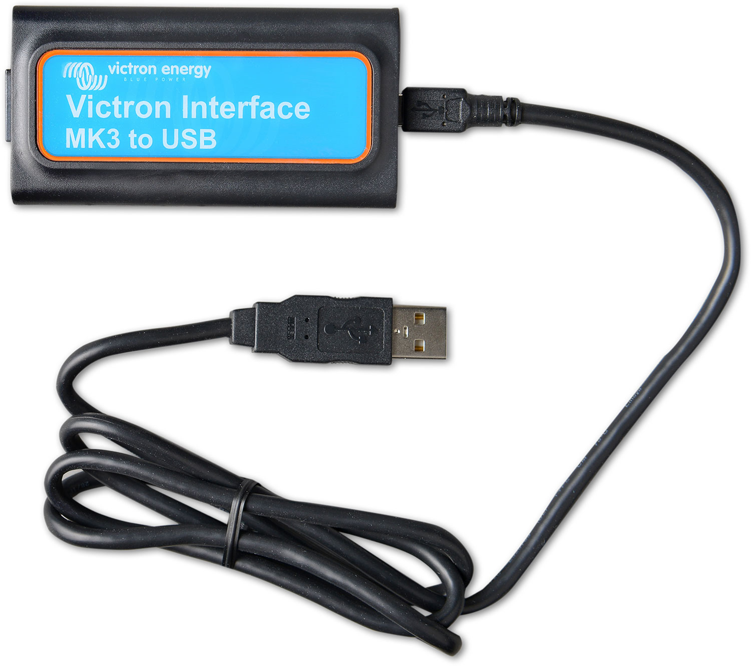
For the MultiPlus, I first had to purchase the Victron MK3-USB Interface. This converts the RJ-45 port on the MultiPlus to a USB connector for connecting to a computer and is required for updating the firmware on these devices, the web-based portal only being usable for configuration changes.
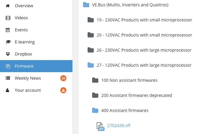
Firmware updates for Victron’s inverters are available on the Victron Professional website. There are a lot of options, so it’s important to match the product type (VE.Bus (Multis, Inverters and Quattros) for mine) and product ID (2702 here) to the corresponding update. The correct firmware will be in the format DDDDVVV where DDDD is the four-digit product ID and VVV is the three-digit firmware version.
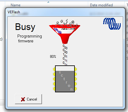
Next, I installed their software in a Windows 7 VM running under Parallels. There are a few components in the overall installer package, including one for actually communicating with the MultiPlus and another one for editing its configuration files. For the purposes of updating the firmware, only VEFlash is used.
To perform the update, I plugged the adapter into my laptop and then into one of the RJ-45 ports on the inverter. Once connected, I ran the firmware update.
Victron MultiPlus Configuration
For the majority of its settings, the MultiPlus cannot be configured via either the Victron app or Color Control GX. Instead, you’re stuck using the dip switch configuration method (very limited) or the VEConfigure program (Windows-only but has everything).
When I first started working on the configuration, it was done entirely in the Windows programs. Since then, Victron has updated their online portal to have the ability to download and upload configuration files (those files are editable within VEConfigure only). This is now the flow I use.
Basics
The MultiPlus settings within VEConfigure are divided into a few different tabs, each focusing on one sub-category of values. I started with a set of recommended values from AM Solar and adjusted from there to match my system.
General
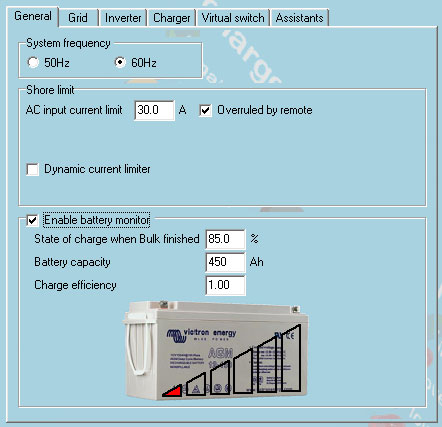
The two settings changed from the defaults here were the AC input current limit (50A default -> 30A to match my trailer) and the enabling of the built-in battery monitor, including adjusting the capacity to match my battery bank.
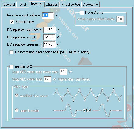
Inverter
I turned on PowerAssist with the default boost factor. All other settings were unchanged.
Charger
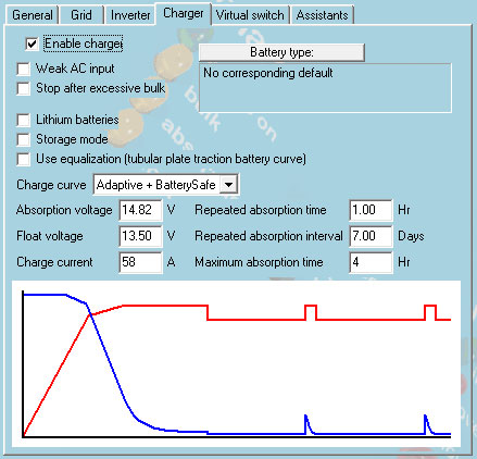
Only the various charge stage voltages and the charge current limit needed to be changed here. The Trojan batteries I’m using want higher voltages than the defaults were set at, and the charge current limit should be 10-13% of the C20 (20 hour capacity) of the battery bank.
Assistants
Victron inverter/chargers have a number of assistants (their term for something similar to a configuration template) to choose from, which change the overall behavior of the units. Most of them are for specialty installations and generally not relevant in an RV, but a few are meant to better tailor it to common installation types. Originally that appears to have been covered by the Hub 1-4 assistants, though those have now been mostly deprecated in favor of the ESS assistant.
Assistants can only be installed/removed via VEConfigure, offering some basic fixed configuration values such as the charge curve. The Color Control GX provides most of the runtime configuration support for the ESS assistant.
Off-Grid
In an off-grid scenario, the solar power will be used first to power all DC and AC loads. Any remaining need will be drawn from the batteries on demand (unless the low-battery shutoff triggers). The ESS assistant does nothing, so it does not matter whether or not it’s installed.
Connected to the Grid
When the MultiPlus is active without the ESS assistant installed, it will use solar to power DC loads only. All AC loads will be powered from the grid, and the inverter will effectively be off. With the ESS assistant installed, it will use the solar power as much as possible to power both DC loads and invert to power AC loads, drawing only the remaining need from the grid.
Caveat: The AC output change from the inverter is not instantaneous, so when the demand drops, some inverted current may end up feeding back into the grid for a few seconds even when the no-feedin option is enabled. From Victron themselves, a true zero-feedin is physically impossible to achieve and this setting just minimizes it as much as possible. This may or may not be an issue depending on where and what you’re plugged into.
Victron’s reason for this is:
An inverter offers a much weaker voltage supply than the public grid does …and that may lead to:
- Flickering lights in certain circumstances
- Inverter shutdown through ‘overload’ when a large load is switched on
With ESS in Optimize mode the system will always remain connected – even when the batteries are full. And although connected, the power draw is not substantial – yet this configuration offers the stability of the grid for nothing.
For my purposes, I configured it to keep the batteries full and without a grid meter device in the system.
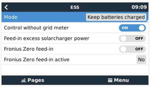
Additionally, when the MultiPlus is in Charger Only mode, the system functions as if the ESS assistant was not installed.
Victron BMV-712 Configuration
The BMV-712 and shunt are responsible for the state of charge monitoring of the battery bank. While it offers a keypad and display for configuration, it’s much easier to do so via the Victron app.
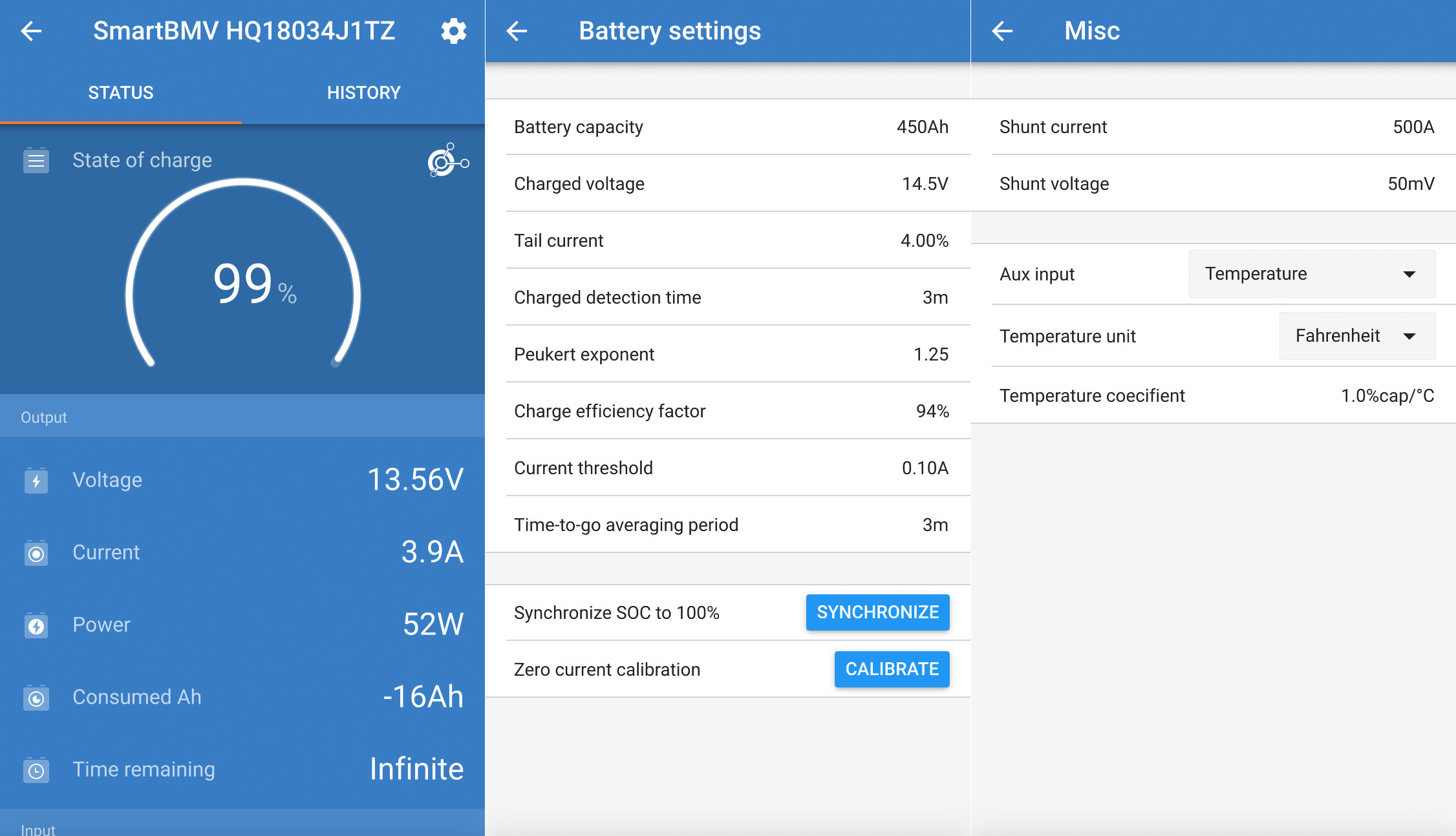
Based both on my own system makeup and recommendations online, I changed:
- Battery capacity to 450Ah
- Charged voltage to 14.5V (AM Solar recommends 0.3V lower than the Absorption voltage, which is 14.82V for me)
- Tail current to 4%
- Peukert exponent to 1.25
- Charge efficiency factor to 94%
- Units to Fahrenheit
- Aux input to temperature sensor
I also created a “VE.Smart Network” so it could share the system state with other components.
Victron SmartSolar 150/85 Configuration
Victron produces an optional LCD screen and control module that can plug into the solar charge controller allowing direct physical configuration, but like the BMV-712, I find it easier to configure via their app.
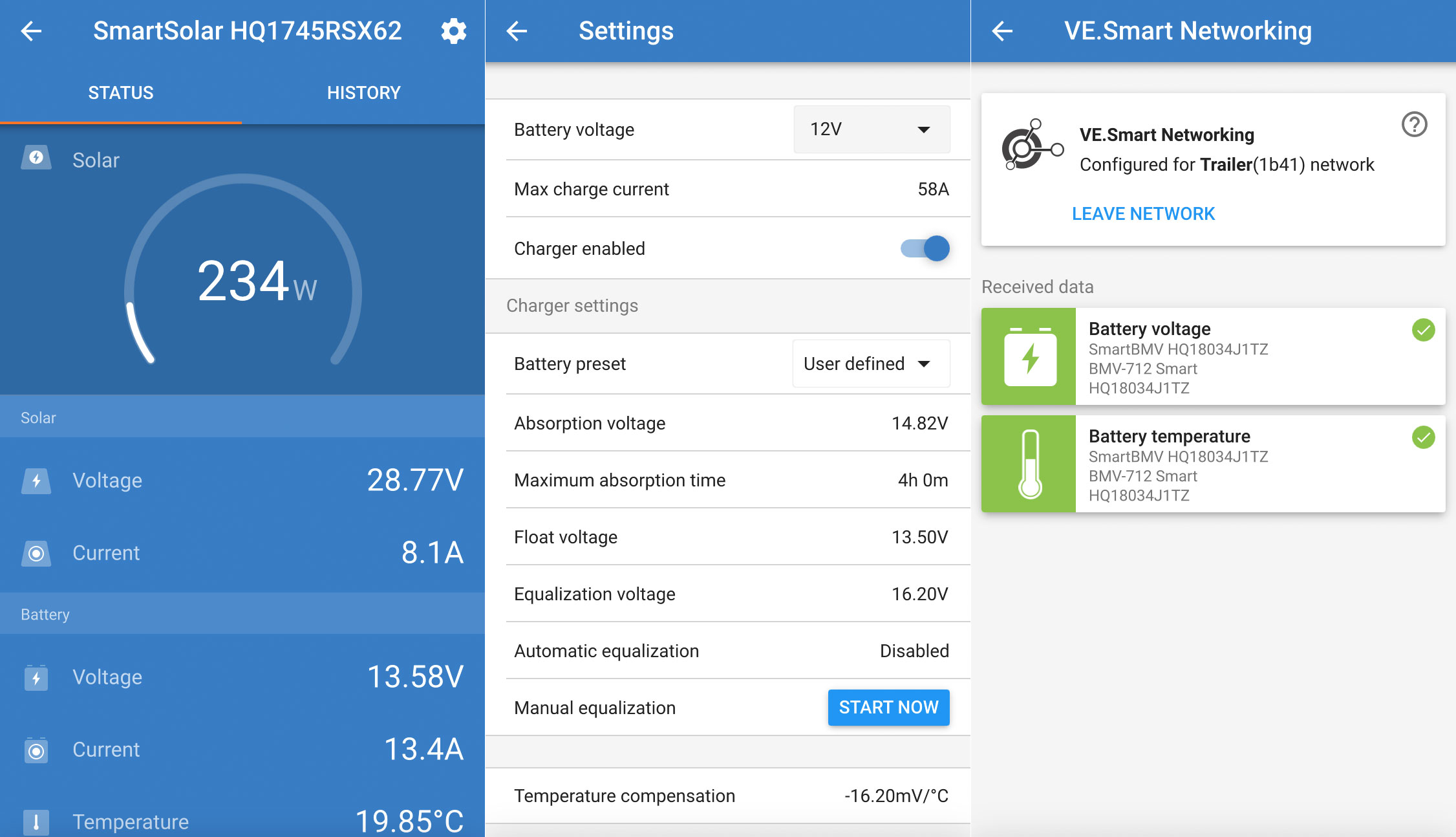
On this I configured:
- Max charge current to 58A (13% of the 20 hour capacity per Trojan’s recommendation)
- Absorption voltage to 14.82V
- Float voltage to 13.5V
I also joined it to the BMV-712’s network.
Conclusions
This configuration effort and education has been ongoing since first finishing the inverter installation a few months ago, each outing giving me more insight into how the system behaves. For as much as I’ve read on it, it has taken using it to actually grok much of what I’ve learned.
The first outing post-install ended up at a dry camping spot near Lolo, MT where I learned that the default voltage cutoffs for the inverter are actually good choices despite appearing to be too low. With a nearly full battery bank, I tried to use a 120V device and immediately got shut down with a low battery warning. After reconfiguring that back to the defaults, it works much better.
A month or two later, I discovered that Trojan had changed the voltage recommendations for the T-105 batteries I’m using because the original recommendations were not allowing the batteries to reach a completely full charge. The booklet I received with the batteries less than a year ago had a bulk voltage of 14.1-14.7V while the new recommendation was 14.82V. In practice I have not noticed any increased water loss, so it’s definitely able to take it.
A month or so after that, I did the solar panel installation and got introduced to a whole new set of configuration options. Surprisingly, very few of those have any significant effect on off-grid use; rather, they mostly control how solar power is used while connected to the grid.
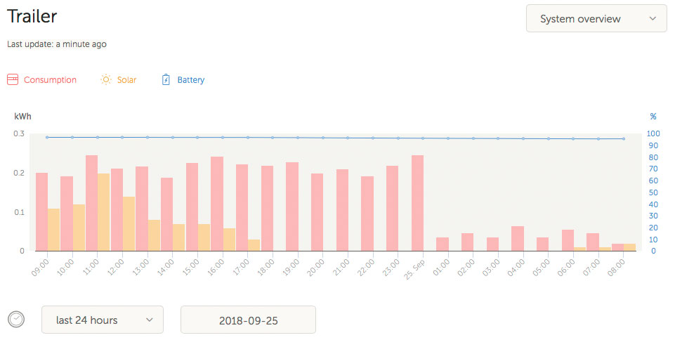
Except when actually boondocking or towing, the trailer is always plugged in. This means that there is virtually always a non-zero cost just to have the trailer parked, whether it’s incurred by the park we happen to be at when traveling or by us when at home. The solar panels are always collecting and converting photons into usable DC current, so it makes sense to use as much of that as possible. That’s where I’m hoping the ESS assistant will help, and so far it’s looking good.
Links
These provided the basis of most information I presented above, though they may not remain live over time.