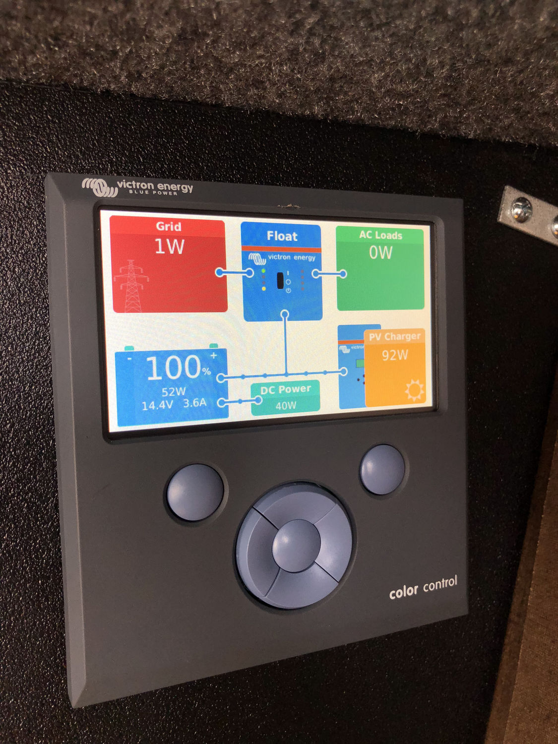
This is the second of several posts about upgrading an RV power system for better off-grid use.
I work remotely. We have no central office, and it’s without exaggeration to say that I can work from anywhere with an adequate internet connection. I’ve worked from my home, a Marriott lobby in Utah, and from the dinette in our trailer in the middle of a forest.
I previously built a full network in the trailer to enable me to easily work out of it, and it has worked out exceptionally well. The only problem is, some pieces of it do not yet have DC-powered equivalents (specifically, my dev server, my NAS, and the cellular bridge), so I need AC power to be fully operational.
As I wrote before, the factory converter/charger by WFCO is incapable of reaching the bulk voltage the Trojan batteries require. The reasons for this are an undersized portion of the factory wiring harness causing excessive voltage drop, and the brains the the WFCO unit are not that smart nor are they configurable (the Trojans currently want 14.82V — this number has been changed in their documentation a couple times). I needed to replace its functionality with something better, which, coincidentally, can be found in the same hardware with an inverter to provide AC power from DC alone.
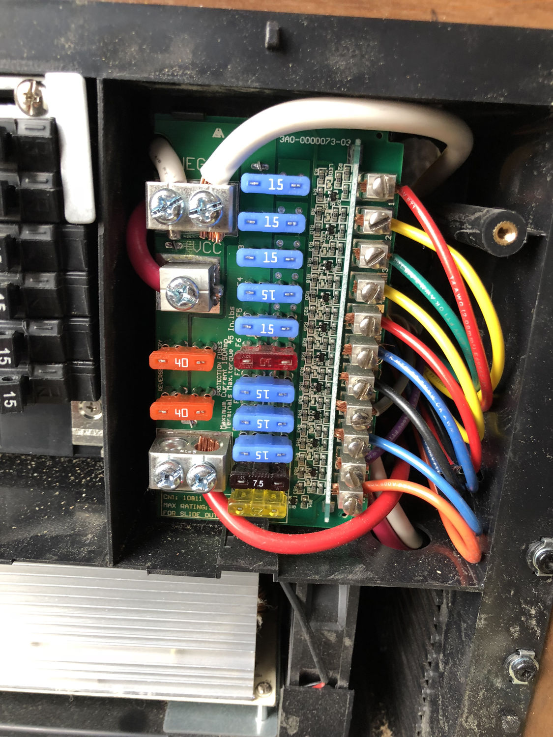
Planning the System
I started by coming up with a list of wants and needs for the system, a little of it based on actual experience and some pieces based on research.
- Inverter. I needed the ability to create AC power without being plugged into the grid or a generator.
- Charger. If I continued to undercharge the batteries with the WFCO unit, I felt I would destroy their potential lifespan. A charger capable of being programmed to Trojan’s recommended settings was a requirement.
- DC voltage regulation. I expected to need to run the occasional equalization on the batteries, and I wanted to be able to do that without disconnecting the rest of the system. Later, in actual use, this didn’t end up being very useful, so I probably wouldn’t spend the money on it again.
- Solar charging. I didn’t intend to do solar at this stage, but I knew I would at some point and wanted to make allowances for it.
- Larger cabling. I definitely needed larger cables to the battery, and the main factory cabling to the fuse block was 6-8 AWG, which introduced more voltage loss than I wanted.
- Battery monitoring. I wanted the ability to monitor the state of charge without doing rough voltage calculations, which isn’t possible while charging anyway.
The initial direction I was going in had a Magnum inverter/charger at the top of the list. As I researched the other pieces, I continually found Victron at the top of the list, so I ultimately chose their inverter/charger to end up with a system where all pieces could be centrally managed because of the shared ecosystem.
Design and Layout
Large inverters can pull a lot of amperage in a short time, which means big wires are needed. Big wires are expensive, so minimizing the length needed generally is a strong factor in guiding where the installation happens. It definitely was for me.
There are two common areas people with my brand of trailer use: the under-bed storage and the front pass-through storage. I chose the latter, mostly for reasons of not wanting a source of potential noise and heat directly under the bed. This choice also effectively decided the shape and placement of the overall assembly, and as an added bonus, it already had an access hole for much of the wiring.
Wireframing
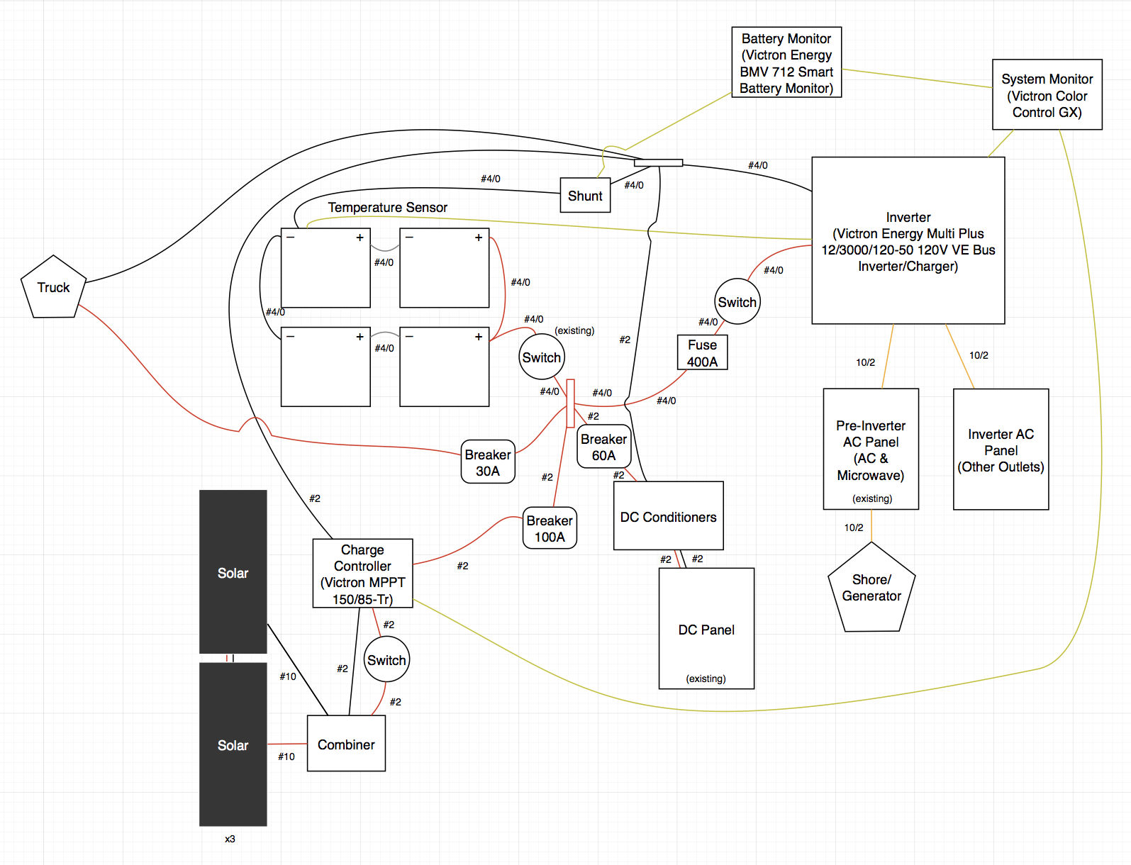
The first layout pass was just to ensure every piece was accounted for. The big pieces are easy (e.g., the inverter), but I didn’t want to forget any of the small ones: switches, bus bars, fuses, and so on.
It was at this stage I chose the various major components:
- Victron MultiPlus 3000 Inverter/Charger
- This is the heart of the system. It will take over the role of the charger/DC converter from the WFCO unit while also providing inverter functionality. At 3000 VA (not watts — it’s rated for 2400 watts under normal conditions), this can effectively power anything I’d throw at it.
- Victron SmartSolar MPPT 150/85 Charge Controller
- The sole purpose of this is to take input from solar panels and use it to feed DC power of the correct voltage into the rest of the system, powering both the DC devices and charging the batteries. I chose this because the 150V limit on panel voltage would allow me plenty of margin for connecting panels in series, and the 85A limit on capacity would be enough for the number of panels that will fit on the trailer.
- Victron BMV-712 Smart Battery Monitor
- This was not my first choice, but it’s what ended up in the final system. Originally I had gone with the Victron VE.Net Battery Controller, but I later discovered that was for an older protocol (despite still being sold) and would not work with the system as I wanted. Of course, I had already purchased it and was well past the return window when I realized that.
- Victron Orion 12/12-360W (2x)
- These take an input between 9V and 18V and convert it to an output of 12.5V. The goal with these was to allow the system to equalize (16.2V for the Trojans) without needing to disconnect anything because of the higher voltage. Problem is, equalization is much rarer to actually need than I initially believed, and many electrical components of the trailer ground at weird places with a variety of voltage drops so they’re hard to fully utilize. I will probably remove them at some point since they introduce an inefficiency and a heat source.
- Victron Color Control GX
- This control panel ties everything together so it can share data, also providing some configuration. Additionally, it also provides the data logging and remote network interface functionality.
Scale Layout
Following that, I did a scale layout of everything. This was to ensure that it would all fit in the space I had to work with, to get a rough idea for the amount of wire and number of connectors needed, and to determine how large of a backing board to get.
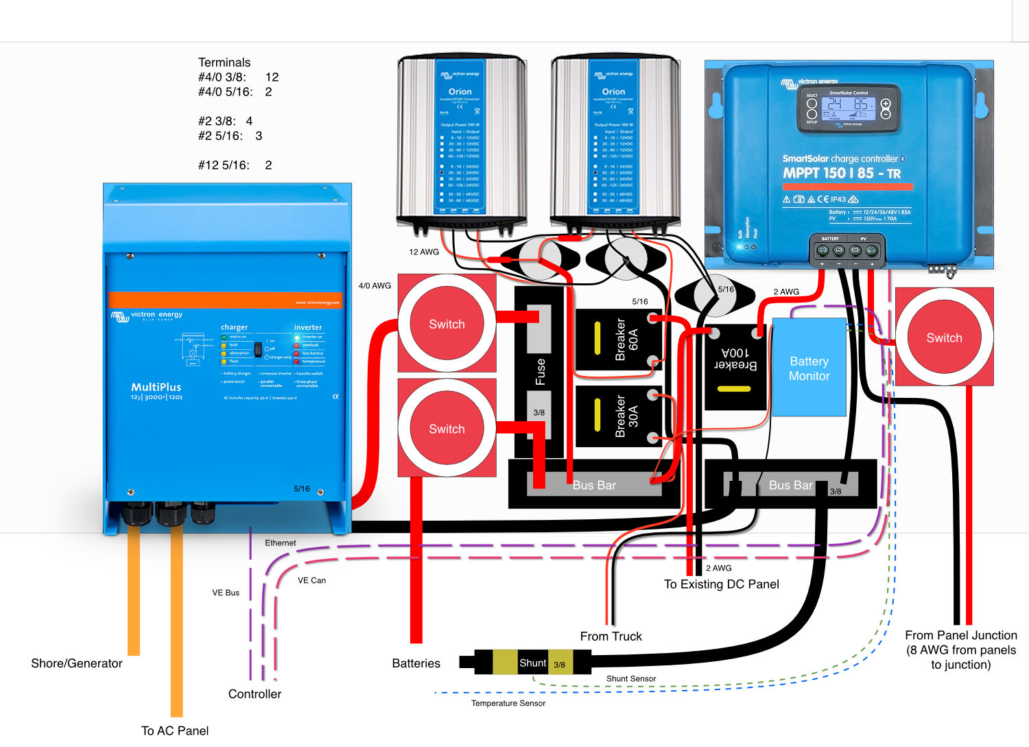
Trial Layout
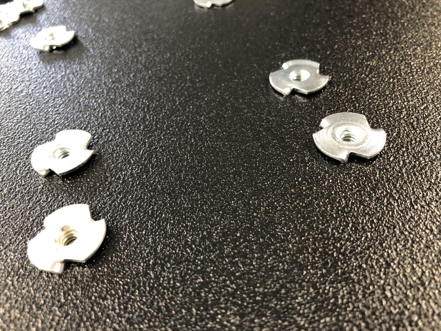
The sole purpose of the trial layout was to ensure my drawing was accurate. I used a sheet of OSB, cut to the height of the pass-through storage, and each component was mounted with tee nuts and #10/24 stainless machine screws. I chose this route because it would allow future unmounting of any part from the front while avoiding regular screws stripping.
Mounting of many of the components was dictated by the wiring more than anything. 4/0 AWG wire is very inflexible, and I actually ended up needing link bars in the wiring between the disconnect switches and main fuse. Even 2 AWG is stiff enough to generally require more sweeping curves than I’d have liked.
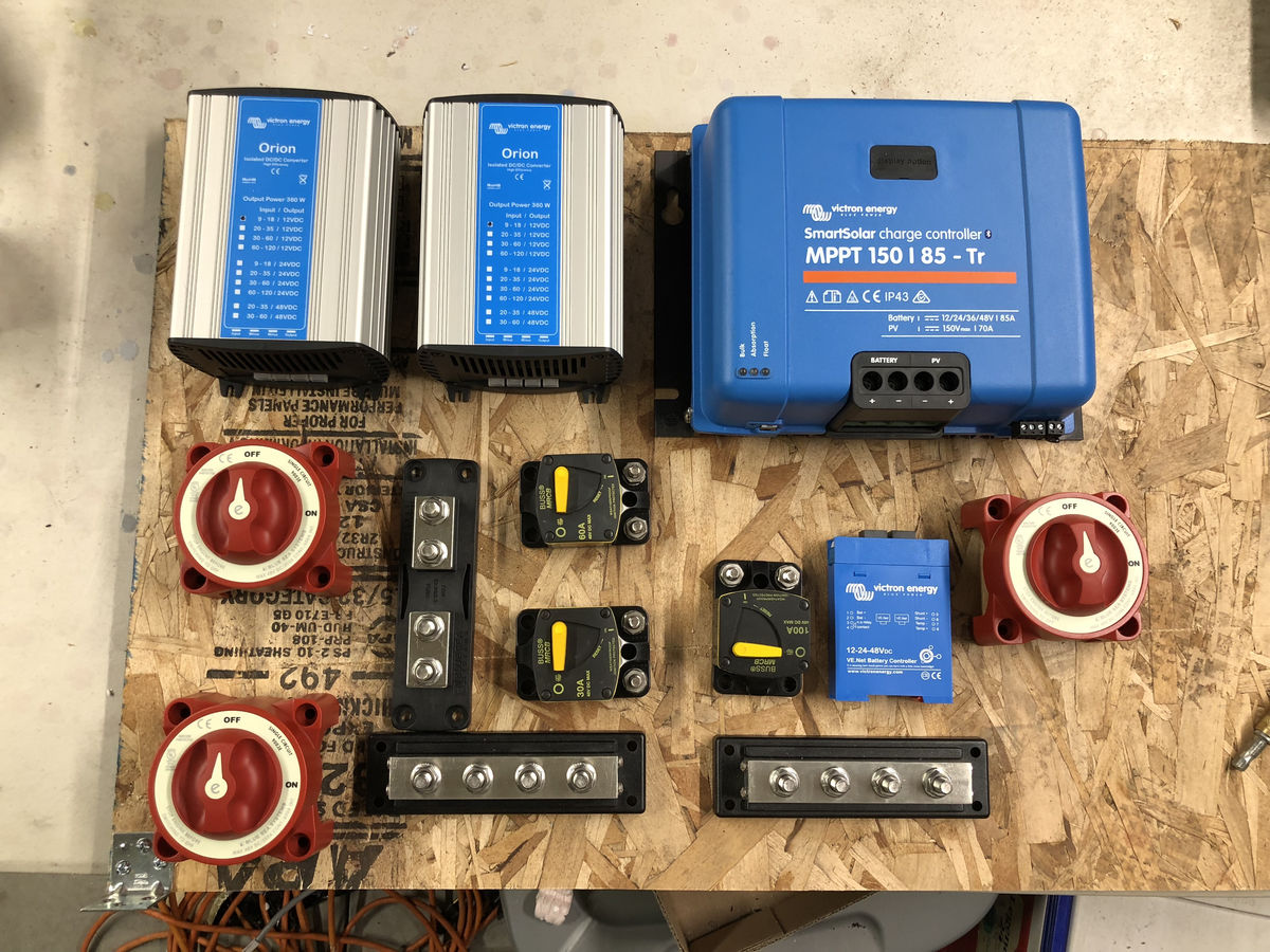
Circuit protection was achieved via a combination of breakers and fuses:
- 400A DC fuse for the inverter
- 30A DC breaker for the trailering harness power supplied by the truck’s alternator
- 60A DC breaker for the trailer’s DC system
- 100A DC breaker for the solar charge controller’s output into the system
Final Assembly and Installation
There were three main steps for the final part of the project:
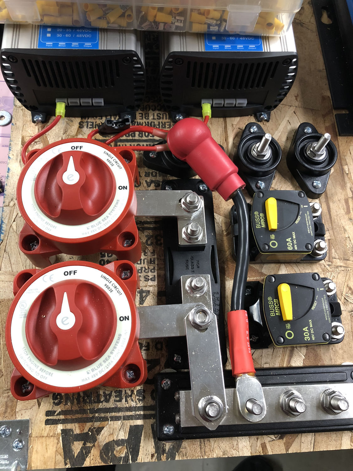
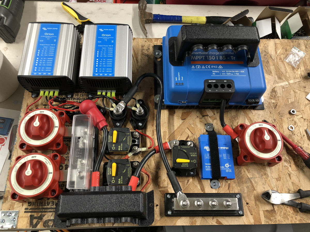
- Transfer the components from the trial layout to the final HDPE backing. I chose a sheet of black HDPE for the final installation, mostly because it looked more clean that way. It is not a cheap material, though it is within the realm of realistic.
- Run two 10/2 romex cables for AC to and from the inverter/charger and a pair of 2 AWG for DC to replace the factory’s 8 AWG pair.
- Mount the final panel in the pass-through storage and connect it into the system.
HDPE Mounting
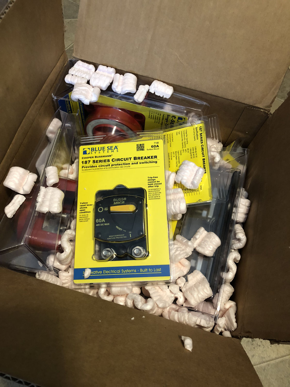
Transferring the components was mostly uneventful, though this was the stage where I realized the 48 VDC limit of the Blue Sea disconnect for the future solar panels would be insufficient after I had already drilled in the holes and mounted it. That was replaced with a DC breaker with a much higher voltage rating.
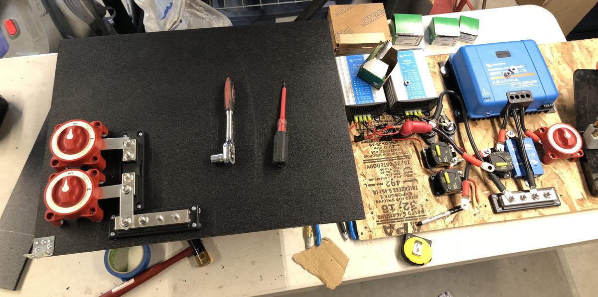
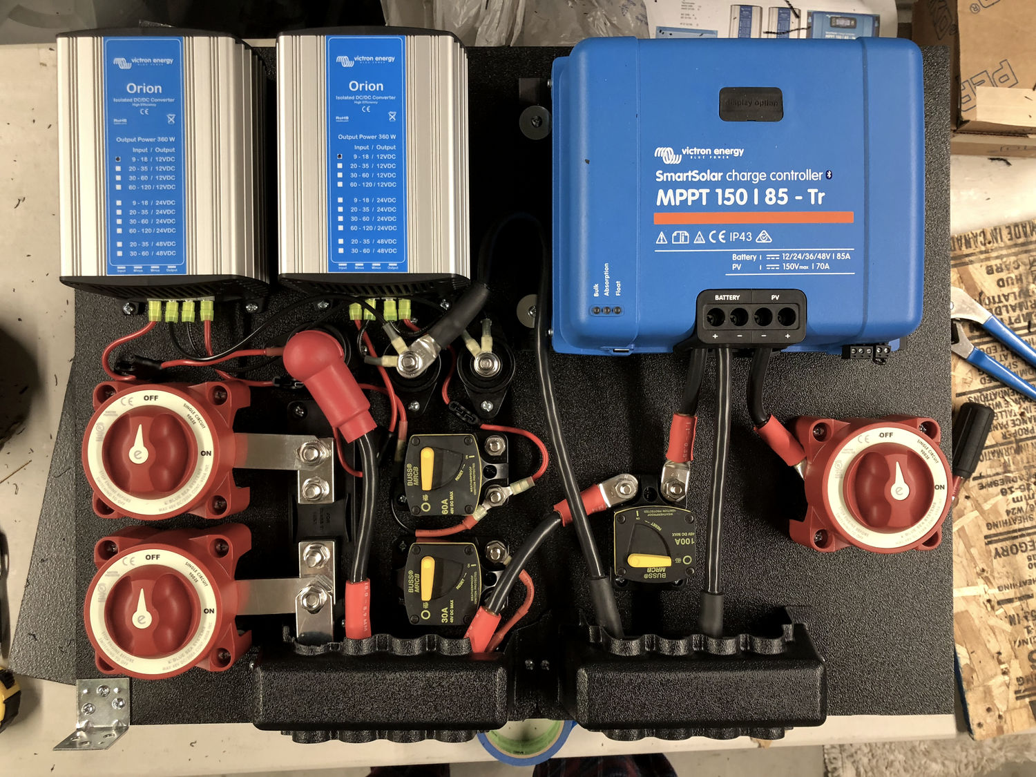
You may notice differences in the component assortment at various stages. These were due to discovering some choices won’t work, such as the VE.Net Battery Monitor.
Additional Wiring
Having the inverter/charger take over the role of the WFCO unit meant needing to run AC cabling to it, and I also wanted to run larger gauge wire to the DC system to reduce the voltage drop. Additionally, I needed to connect the new panel and inverter to the batteries.
Originally, I had thought I was going to need to run my wire in flex conduit on the underside of the frame, but I discovered a route from behind the converter, through an existing hole in the floor, and into the cavity between the floor and lower coroplast.
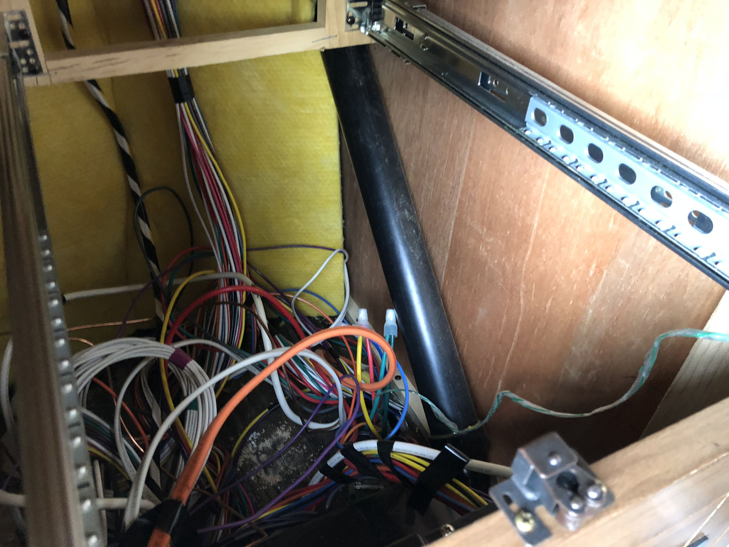
I started by running a fish tape through the hole behind the converter. This got me through the plywood, but below that is a layer of fiberglass insulation and some type of black, breathable fabric. That needed a hole cut to allow the fish tape through, so I had to cut an access port into the coroplast at the edge of the black tank in order to reach it. Coincidentally, this access port also doubled as a pull point to route the new wires around a brace.
Note: when cutting into the coroplast, it’s best to only cut on three sides, leaving the edge towards the front of the trailer intact and just folding on it. It’s much easier to re-seal and stays sealed while traveling.
Using the fish tape, I pulled in a pull string from the lower power junction. This got attached to the bundle of new wires and pulled through.
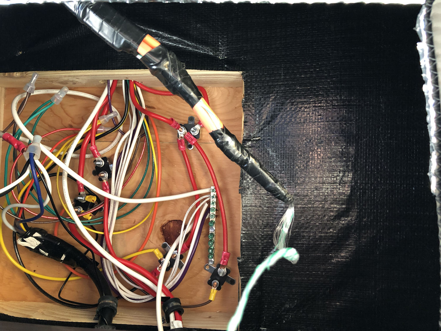
Installation
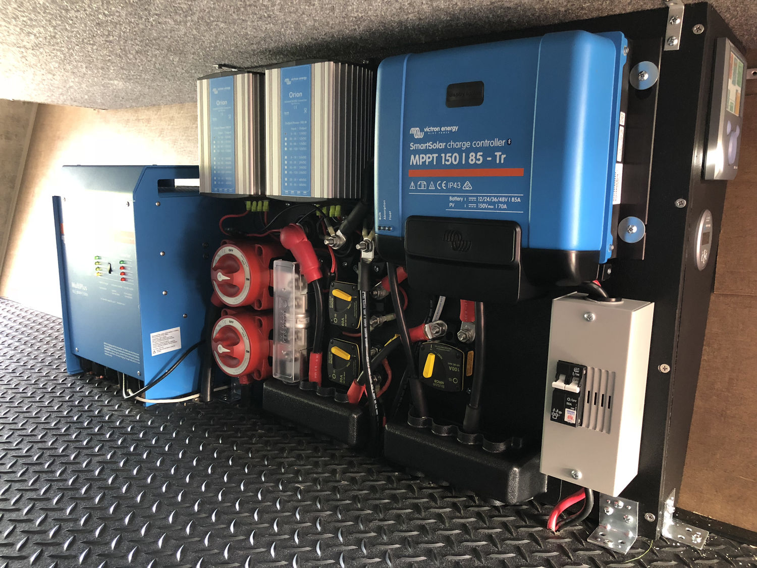
Due to the stiffness of the wiring, I positioned the inverter/charger directly over the lower power junction, cutting and drilling the holes required to bring the two AC cables and two DC wires up. The AC in from the shore went to the AC in of the inverter/charger, the AC for the house system to the first AC out, and the two DC wires to the positive and negative terminals. I also installed the bundled temperature probe on the battery negative terminal as indicated.
With this in place, I was able to position the HDPE panel and drill its holes through the pass-through floor. I had originally intended to pass everything through the same hole, but the wire stiffness made that impractical, so I ultimately made more smaller ones where needed and dropped the wires down straight. The floor penetrations included a 4/0 AWG each for the positive and negative bus bars, the 2 AWG DC pair out to the house system, and the 4 AWG DC pair in from the solar panel wiring junction.
After getting the wires in place, I anchored the panel with several angle brackets. I finished the remaining interconnects and started powering things up. Thankfully, there was no surprise magic smoke, and it went fairly smoothly.
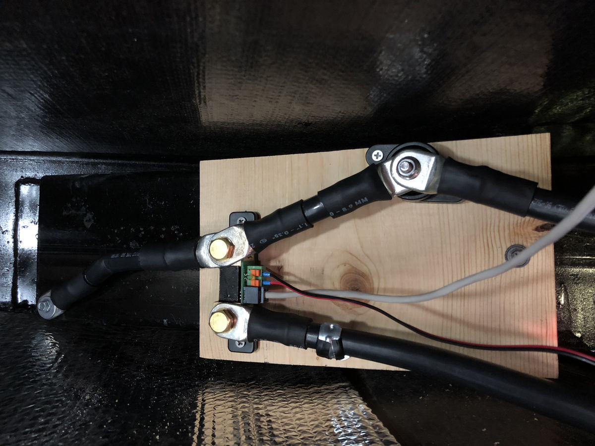
In addition to the pass-through installation, there were also a few additions between the coroplast and floor. On one side of the tongue I installed the shunt, and on the other side I placed two junction points, one for the raw solar and one for the house DC feed.
Configuration
I plan on going into more detail into this sometime in the future because much of it requires some actual experience in the field to fully understand, but I started out by doing a few things:
- I updated the firmware on everything. The battery monitor and solar charge controller are really easy to do via the app, but the MultiPlus requires purchasing the Victron dongle, downloading the correct firmware, and using their Windows-only software to run the update.
- Charge voltages and battery capacity were set on everything.
- The Color Control GX was joined to my network and signed into my Victron account for history collection.
